Linear or six-axis robot? How to choose the right robot for an injection moulding machine
The question is almost always framed as a choice of robot type. Yet the decision is not made by the robot. It is made by the task: the cycle time, the motion path, the installation geometry, and what happens to the part after it leaves the mould.
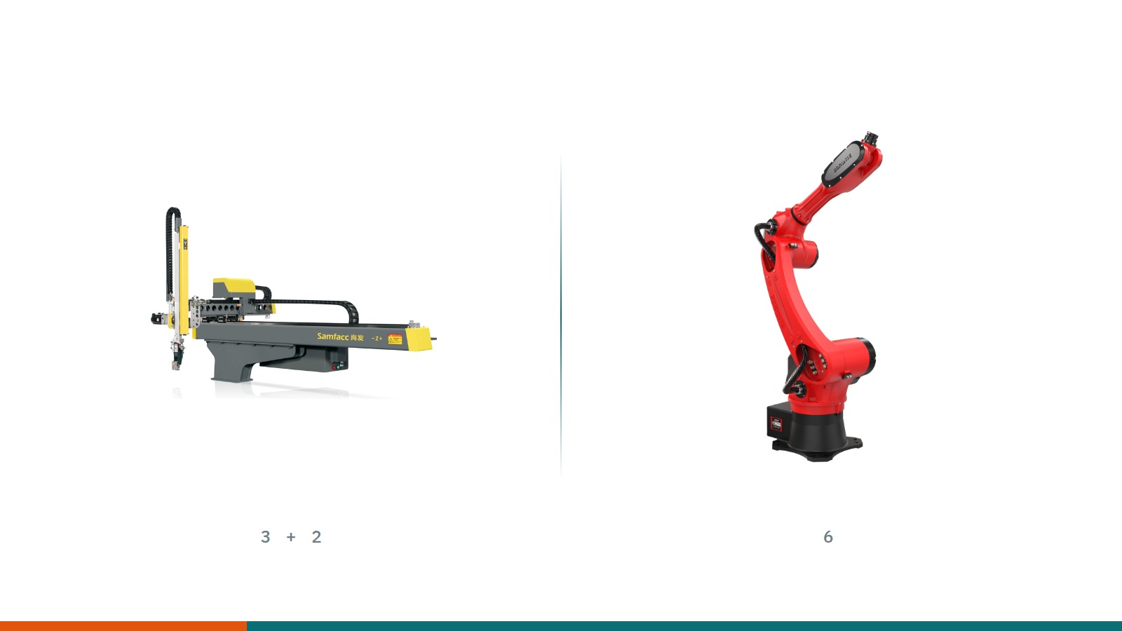
If you are looking for automation to go with an injection moulding machine, you will soon receive the same two quotations. One is a linear take-out robot mounted on the machine, the other a six-axis articulated arm. The price difference is noticeable, and the two suppliers will give you opposing reasons for the same task.
There is a reason for this. Robot manufacturers' technical material describes the strengths of their own design, and the two camps dispute partly the same applications with each other. This debate cannot be settled in general terms. What can be stated is which six questions settle it on a specific machine. Before that, it is worth clarifying how the two designs are actually built, because most misunderstandings start there.
01. What is a linear take-out robot, and how does it move?
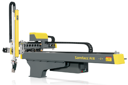
A linear robot (also called a Cartesian or traverse robot) moves along three mutually perpendicular straight axes. It has no rotary joints, which makes its structure easy to describe and highly repeatable.
- Traverse motion: the long-stroke main axis, which stands perpendicular to the machine axis. From a position above the mould area it carries the part out of the machine, to the side.
- Kick motion: a short stroke parallel to the machine axis. It positions the gripper over the cavity and strips the part off the cores.
- Vertical motion: the descending arm that takes the gripper down between the mould halves.
This geometry explains two practical properties of the equipment. The traverse beam is mounted on the fixed platen, not in the middle of the mould area, and it overhangs the machine on one side only. It follows that the robot cannot reach the injection side of the machine, and that the part is deposited not along the machine but to the side, next to the mould area, typically onto a conveyor or into a box placed beside the machine.
There is a named exception. In an axial layout the long beam runs lengthwise over the top of the machine, and the robot deposits at the end of the machine. This comes up when the free aisle between machines has to be preserved, because it allows machine rows to be installed closer together. In exchange, it needs space behind the machine.
Manufacturers label these axes X, Y and Z, but the assignment of the letters is not standardised. When comparing quotations and when programming, always follow the documentation of the particular robot rather than the letter.
The same applies to the axis count. In some manufacturers' classifications the sprue arm appears as a separate axis in the designation, so a "five-axis" traverse robot does not necessarily mean five freely programmable axes; it may mean a three-axis base machine with a main arm and a sprue arm. When comparing quotations, the itemised list of axes is the usable figure, not the number in the model name.

The vertical arm may be single-stage or two-stage. A two-stage (telescopic) arm is lower when retracted, so it fits into a low workshop, while its reach downwards stays long. In practice this detail often matters more than any catalogue figure.
One misunderstanding is worth clearing up here. The linear robot is often called a "simple take-out unit", as opposed to the "flexible" articulated arm. The three straight axes can, however, be extended with one or more servo rotary axes, and the robot can then rotate the part, load inserts, deposit in an ordered pattern or hand over to an inspection station. The difference is not the presence of capability but the nature of the motion.
Variants of the linear familyA sprue picker lifts out only the sprue and runner system, with short strokes. A traverse take-out robot also removes the part and carries it outside the machine. A side-entry robot enters the mould area horizontally rather than from above: where the workshop is low, or where a label has to be placed into the mould, this is the design that comes up. Vertical injection moulding machines take arms of a different geometry again.
The dual-arm layout deserves separate mention. Here the carriage takes two vertical arms: a main arm for the part and a shorter, simpler sprue arm for the sprue and runner system. There are two reasons for this. First, the two do not go to the same place: the sprue typically goes to a granulator or a separate bin, the part onto a conveyor or an ordered tray. Second, with a three-plate mould the runner system separates in its own parting plane, so it physically has to be removed separately. The two arms thus complete both tasks in one cycle, in a single entry into the mould.
02. What is a six-axis articulated robot, and how does it move?
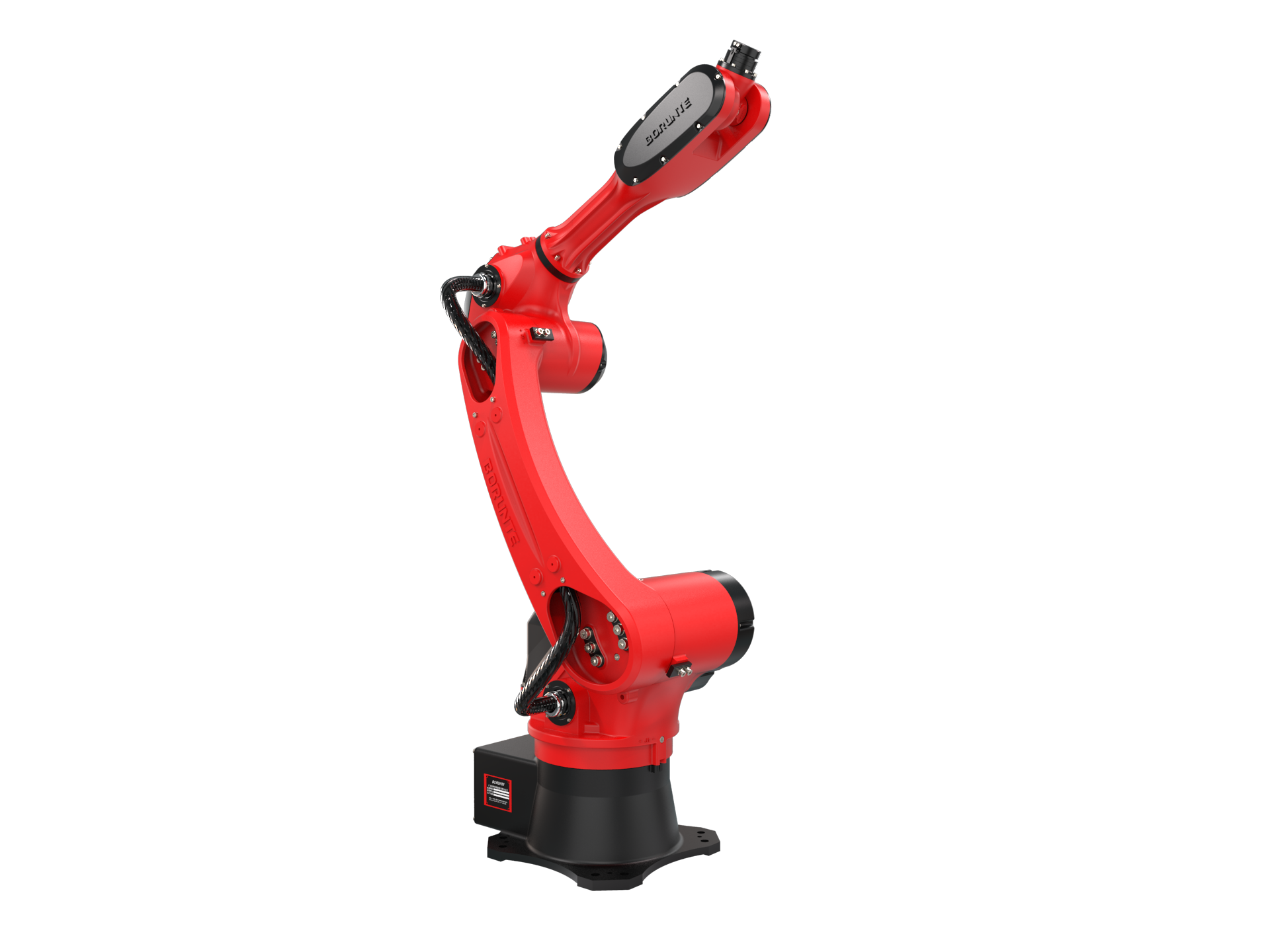
A six-axis robot consists of six rotary joints. The links between the joints are rigid, and the position of the tool centre point is determined by the combination of the six joint angles. Three properties follow from this, and all three matter in an injection moulding cell.
The working envelope is near-spherical, not a box
The articulated arm reaches above itself, below itself, to the side and partly behind itself. The working envelope is therefore a near-spherical, complex volume whose actual shape is set by the motion limits of the individual joints, and typically not every point in it can be reached in every orientation. This is an advantage for motion inside the cell, but it calls for attention when it comes to space: without limiting, the robot can reach points where it has no work to do. How much safeguarded space that turns into is a design question, not a property of the construction. We return to it under the fourth factor.
The rated payload on its own is not enough
The kilogram figure in the headline of the data sheet is the upper limit of the total mass that can be mounted on the wrist flange, and it includes the gripper, the adapter plate, the cabling and the part. That, however, is only one of three conditions. The manufacturer's documentation also specifies the permissible distance of the centre of gravity from the wrist flange, and separately the permissible mass moment of inertia. KUKA's manuals, for instance, state explicitly that both values must be checked in every case, and the manufacturers' sizing tools likewise perform the static and dynamic load check on the basis of mass, centre of gravity and inertia.
The same ten kilograms held close to the flange and extended three hundred millimetres to the side do not represent the same load on the joint drives. A long, asymmetric gripper can therefore fall outside the specification even when its mass stays below the rated figure. Then there is the dynamics: the required acceleration and the inertia of the moved mass together decide whether the robot can carry the load at the intended rate.
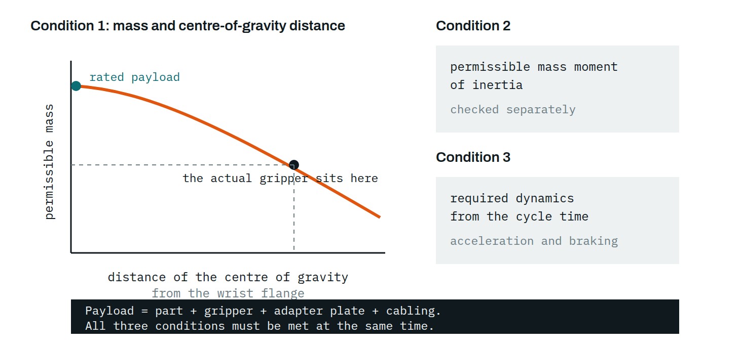
For a request for quotation, therefore, the figure to supply is not the kilogram but the planned mass of the gripper, the position of its centre of gravity relative to the flange, and the motion requirement arising from the cycle time. With these the manufacturer or the integrator can run the check.
Repeatability is not the same as accuracy
The figure on a robot manufacturer's data sheet is typically repeatability: how closely the robot returns to the same point in successive cycles. It does not tell you how accurately it reaches a programmed coordinate. For take-out work repeatability is the relevant figure, because the robot travels to taught points. If camera-based position finding or an external coordinate system enters the cell, however, absolute accuracy becomes a question as well.
03. There are several steps between the two
The choice is not binary. At least three intermediate solutions exist, and a significant share of real cells are built from them.
- Linear robot with a servo wrist. One or two rotary axes are added to the three straight axes. The part can then be rotated, a part ejected at an angle can be removed, and the deposit can be oriented. The speed of the straight axes is retained.
- Articulated robot on a rail. The articulated arm travels along a horizontal beam. The spherical envelope is thus combined with linear transfer, and the arm can serve several machines.
- Division of labour. A linear robot takes the part out at the machine and hands it to an articulated arm, which performs the downstream operations. This arrangement has long been established, and the literature treats it as a solution in its own right rather than a compromise.
A point of terminologyIn everyday use, "collaborative robot" denotes a type of machine. In the terminology of ISO 10218:2025 the collaborative character is a property of the application, not of the robot. The same arm can be used in a conventional industrial application behind a fence, and in a collaborative application in a shared workspace. What separates the two is the risk assessment and the protective measures, not the manufacturer's product category.
04. Six questions that decide it
1. How much time is available, and when?
There are two different time windows here. One is the mould-open window: the time during which the mould is open and the robot has to enter, grip the part and come out. Whatever cannot be overlapped with another machine motion in this window adds directly to the cycle time. One of the aims of the newer machine-to-robot interfaces is precisely to reduce unnecessary waiting. The other window is the remainder of the cycle, while the machine works with the mould closed: during this time the robot can operate freely outside the machine without holding up production.
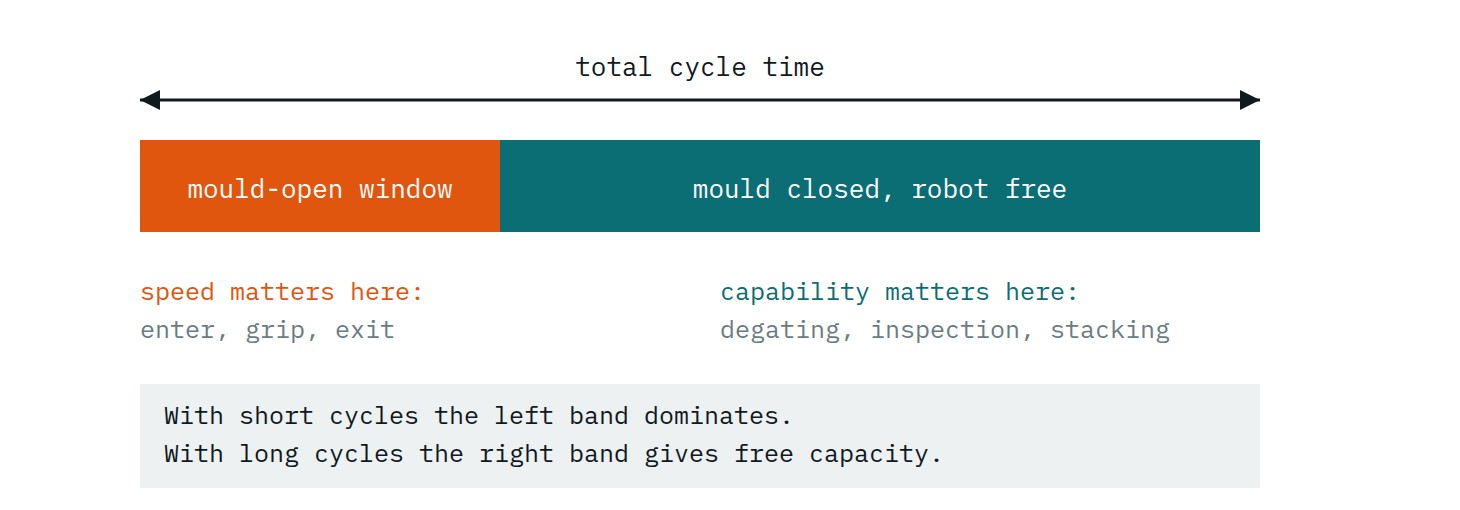
In short-cycle, high-volume production (typically thin-wall packaging products) the mould-open window is tight, and practically nothing else fits into it. Here the advantage lies with a short, direct motion path optimised for this task, which is why side-entry solutions have become widespread in this field. With longer cycle times, on the other hand, the robot has nothing to do at the machine for the greater part of the cycle, and it is this free time that an articulated arm can spend on downstream operations.
What not to conclude from thisThe fact that linear solutions have become widespread in short-cycle work does not mean that an articulated arm is always slower at take-out. In one documented automotive case of its time, on a 1,500 tonne machine, an articulated robot brought the part out in less time than the linear solution used there, because the low headroom of the building constrained the geometry of the linear robot. A single case in a single plant cannot be generalised, and neither can the reverse: it has to be measured on your own machine with your own mould.
2. How heavy is the load, where is its centre of gravity, and how fast must it move?
The mass of the gripper is just as much load as the part, and with a multi-cavity mould it soon becomes heavier than the product itself. Its geometry determines the position of the combined centre of gravity, which acts differently on the two designs: on an articulated robot it affects the permissible centre-of-gravity distance and the moment of inertia, on a linear robot the bending of the vertical arm and the freedom of the motion from oscillation.
It is therefore worth designing the gripper and the robot together. If the gripper is finished first, the sizing of the robot is constrained; if the robot comes first, the gripper designer works within a fixed budget, which is not always communicated.
3. Does the part have to be rotated or manoeuvred around obstacles?
If the product can be ejected in a straight line and the deposit is also straight, three axes are enough. If the direction of ejection is angled, if the part has to turn in the mould or during withdrawal, or if it has to be carried past a tie bar, a slide or another obstacle, a rotary axis is needed. That still does not mean a six-axis robot: one or two servo rotary axes often solve it.
4. What do the building and the machine allow?
Four figures decide this: the free headroom above the machine, the lifting height of the crane, the free floor area around the machine, and the required mould opening stroke. On floor area, note that with a linear robot the traverse beam also projects sideways beyond the footprint of the machine, so the distance to the neighbouring machine or the width of the aisle can be a constraint. This is the point at which the axial layout comes into consideration.
The mould opening stroke is easily left out of the planning. The thickness of the arm entering the mould area from above determines how far the mould has to be opened for the robot to fit, and a longer opening stroke means a longer cycle time. This is why articulated robots are also built in slim-arm versions designed specifically for injection moulding.
On floor area it is worth separating four concepts, because they blur together in everyday use, and this is the source of the belief that the full reach circle around an articulated robot always has to be fenced off. ISO 10218-2:2025 distinguishes the maximum space (everything the moving parts of the robot can reach), the restricted space (the part of the maximum space that has been reduced by limiting devices), the operating space (the part actually used by the programmed motions) and the safeguarded space (where the safeguarding is effective).
Limiting can be done with mechanical stops or with safety-rated software space reduction, and the safeguarded space can thereby be matched to the useful motion. The restricted space has to stay within the safeguarded space, whereas the maximum space may extend beyond it, which is precisely why limiting is needed. With a floor-mounted articulated robot, an unlimited installation often does result in a larger cell area, but that is a design question. At the enquiry stage, then, the question to ask is not the size of the reach circle but whether the supplier plans any space reduction, and by what means.
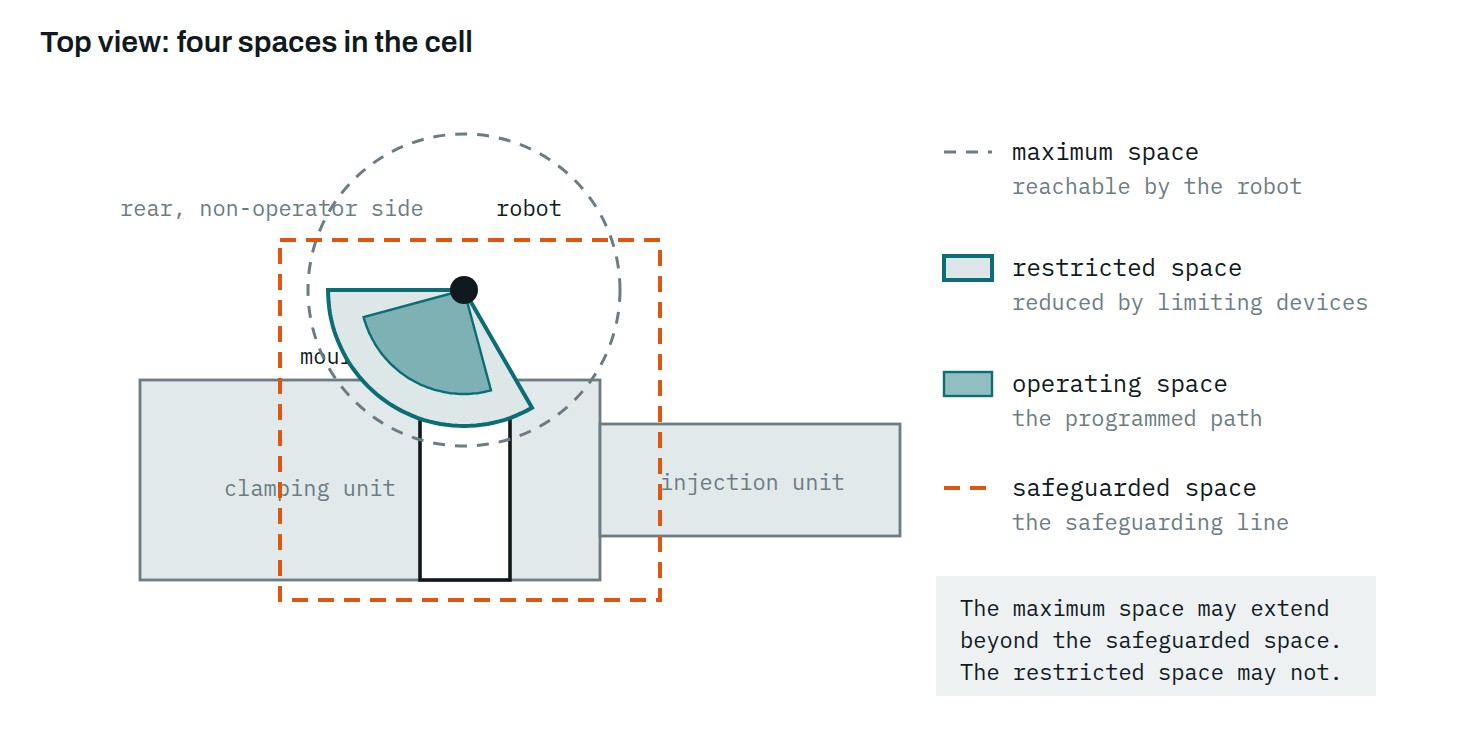
It is worth seeing the proportions realistically. An articulated robot placed at an injection moulding machine typically stands beside the mould area, on the rear, non-operator side, and it is small compared with the machine: a reach of about a metre and a half is a fraction of the length of a mid-size machine. Space requirement therefore does not grow because the robot is large, but because it reaches in several directions; without appropriate space limiting, a larger safeguarded area has to be allowed for.
5. What happens to the part after take-out?
The most important of the six questionsIf you can ask only one question before selecting a robot, ask this one. It is what turns the decision from robot selection into cell design.
This question settles more cases than all the others. If the part goes onto a conveyor or into a box, take-out is the whole task. If, however, the sprue has to be separated (which with a dual-arm linear robot can already be handled at the machine), the part measured, assembled, fitted with an insert, stacked in order or boxed, then the content of the cell grows. There are then three routes: more linear axes, an articulated arm, or the two in a division of labour.
6. How often does the product change?
For single-product, long-run production, rigid automation of the dedicated-machine kind is cheaper and faster. If, however, moulds are changed weekly or daily and the geometry of the products also varies, the value of a re-teachable, programmable solution grows, because the equipment can also serve the next job. With frequent product changes it is therefore not only the programmability of the robot that counts, but also gripper changeover, the resetting of ancillary equipment and the time needed to teach the new program.
The six questions in one line each
1. Length of the mould-open window short → short, direct path 2. Load, centre of gravity, dynamics all three conditions together 3. Need for orientation yes → servo rotary axis or more 4. Headroom, floor plan, opening tight → side-entry or slim arm 5. Downstream operations many → articulated or shared work 6. Frequency of product change frequent → re-teachable solution
05. What the quotation does not include
The price of the robot is not the price of the cell. The items below regularly appear on a separate line or nowhere at all, while they materially affect the cost and the timing of the investment.
| Item | Why it is a question |
|---|---|
| End-of-arm tooling | Product-specific, and typically not made by the robot manufacturer. Its mass feeds back into the sizing of the robot, so the two decisions are connected. |
| Machine interface | EUROMAP 67, still in wide use, defines a hardwired electrical interface between the injection moulding machine and the robot. EUROMAP 12 appears mainly when replacing older equipment, and its connector is not the same. In the newer OPC UA based architecture, data exchange is handled by EUROMAP 79 (identical to the OPC 40079 recommendation), which is currently at Release Candidate status. |
| Safety signals | A separate matter from the operating signals, and they stay outside the OPC UA interface. EUROMAP 81 defines a hardware interface for this purpose. For connecting external safety devices, EUROMAP 78 applies; EUROMAP 78.1 extends it with additional signals that let the injection moulding machine verify the presence of a double acknowledgement system. |
| Safeguarding | Fence, door interlocking, light curtain. With an articulated installation the area to be covered is typically larger. |
| Cell documentation | Risk assessment, operating instructions in the local language, and, if the system qualifies as an assembly of machinery, a declaration of conformity for the system as a whole. The next section deals with this. |
| Training | Who can modify the program after a mould change, and in what interface language. |
06. Who will be the manufacturer of the cell?
If the injection moulding machine and the robot are integrated in such a way that they perform a common task, their operation interacts, and their controls are interconnected in a safety-relevant manner, the resulting system may qualify as an assembly of machinery and become a unit of conformity assessment in its own right. The guide to the application of the Machinery Directive lists these three conditions, and the classification is always a matter of case-by-case judgement. This is one of the least frequently asked questions in a procurement, yet it determines how liability is distributed.
The safety standard series for robots was revised in February 2025. Part 1 of ISO 10218 deals with the robot itself, as partly completed machinery: equipment that is not in itself intended for the proper operation of a specific robot application, but is integrated into a robot application or a robot cell. Part 2 covers the robot application and the robot cell, and names the integrator as responsible: the party that designs and assembles the cell and is answerable for the safety strategy, the protective measures and the interconnection of the controls. In the language of the standard the integrator can be regarded as the manufacturer of the cell as supplied, and this role may be taken by the equipment manufacturer, an engineering office, the distributor or the user itself.
On the machine side, EN ISO 20430:2020 is the relevant safety standard, having replaced EN 201:2009. That document explicitly names the robot and the take-out equipment as ancillary equipment, and also addresses the protective measures associated with integrating ancillary equipment.
Two further circumstances complete the picture. Applying a standard is voluntary: a harmonised European standard whose reference has been published in the Official Journal of the European Union confers a presumption of conformity for the requirements it covers, but the binding element is always the legal requirement itself. On the legal side, change is coming: Regulation (EU) 2023/1230 on machinery applies from 20 January 2027, and Directive 2006/42/EC ceases to apply. For a cell ordered in 2026 but realised in 2027 it is therefore necessary to establish in advance when placing on the market, or putting into service, takes place, and which legal framework the supplier undertakes to follow for conformity assessment.
Three questions for the request for quotationIf the system qualifies as an assembly of machinery, who issues the declaration of conformity for the complete cell, not only for the robot? Where is the technical documentation of the cell compiled and held, and is the risk assessment part of the supply? In what language will the operating instructions be produced, and which legal framework will they refer to at the time of handover?
These questions are not answered by the country of origin of the robot, but by who in the supply chain takes on the integrator role. Between two cells fitted with identical robots, this can be the largest difference.
07. In summary
| If this describes the task | Start in this direction |
|---|---|
| Short cycle, simple removal, deposit onto a conveyor | Linear take-out robot with three axes |
| Short cycle, low headroom, placing into the mould | Side-entry solution |
| Simple removal, but oriented deposit or angled ejection | Linear robot with a servo rotary axis |
| Part and sprue to different places, or a three-plate mould | Dual-arm traverse robot: main arm and sprue arm |
| Longer cycle, several downstream operations in the cell | Articulated arm, or linear and articulated sharing the work |
| Serving several machines with one arm | Articulated robot on a rail |
| Frequent product changes, varying geometry | Re-teachable solution rather than a dedicated machine |
The table is a starting point, not a decision. Any one of the six questions can override the others: a low ceiling or a heavy gripper is enough for the obvious solution to drop out. It is therefore worth working through the factors before comparing quotations.
08. What we see in the market
Our portfolio covers both designs, with Samfacc linear take-out robots and Borunte six-axis arms, so on this question we do not argue for a single robot type but start from the requirements of the cell. What we observe is that in most investments the question is not which robot is better, but which element of the cell was left out of the planning. Most often the gripper, the increase in the mould opening stroke, and the cell documentation.
For a first screening, some manufacturers, Borunte among them, also state a machine size range for their six-axis models. A model of roughly 1,500 mm reach and 10 kg payload is recommended for machines between 200 and 600 tonnes, and an 1,850 mm, 20 kg version for the range between 500 and 1,300 tonnes. This classification is a quick first filter, but it does not replace the payload diagram and the centre-of-gravity check.
Related articles: Buying an injection moulding machine in 2026, five criteria · EUROMAP recommendations: a reference for machine procurement · Industrial chiller sizing
Take the essentials with you!
Enter your details and we'll email you the download link.
Request a tailored quote!
Fill out the online configurator and our experts will send a tailored offer within 24 hours.
Robot configurator →Got a question? We can help!
Get in touch and our experts will help you choose the right solution.
Contact →