EUROMAP recommendations: what does each number mean? A complete overview
EUROMAP is not a standard. It has no legal force and nobody can be compelled to comply with it. Yet it is the reference system without which machines from two different manufacturers could not be compared — or connected together.
If you have ever looked at an injection moulding machine datasheet, you have come across it. "Size according to EUROMAP." "Energy efficiency class according to EUROMAP 60.1." "EUROMAP 67 robot interface as an option." The numbers are there in every catalogue, yet their meaning is rarely explained, and there is hardly any comprehensive overview available.
This article tries to fill that gap. It does not replace the recommendations themselves, but provides a map to them: which one is for what, which one superseded which, which one is not yet a final release, and which ones are worth knowing when you buy a machine, integrate a robot or build data acquisition.
Recommendation, not law: what this means in practice
EUROMAP is the association of European plastics and rubber machinery manufacturers. Its technical documents are issued by its technical commission, which operates at the German VDMA in Frankfurt. What it publishes, it consistently calls a technical recommendation, not a standard.
The difference is not a formality, but it is not where most people look for it either. Even the application of a harmonised standard is not mandatory. It does, however, have legal significance: if its reference has been published in the Official Journal of the European Union, its application gives a presumption of conformity with the legal requirements it covers. The mandatory element is the legal requirement itself, not the application of the standard, and conformity can also be demonstrated by other technical solutions. A EUROMAP recommendation has no such legal role at all. A manufacturer is free to wire its robot interface connector differently. That does not make its machine non-compliant, only incompatible.
It is precisely this mechanism that keeps the system alive. A recommendation works because non-compliance hurts the manufacturer: its machine cannot be connected to the existing robot, its energy figure cannot be compared with the competitor's, its mould changer does not fit. The pressure is commercial, not legal. That is why we use the term de facto industry standard: the major machine manufacturers and the robot and peripheral makers all align with it as if it were mandatory.
With the newer, OPC UA-based recommendations the situation is even stronger. These do not merely resemble the international specifications, they are identical to them in content, matched release by release. EUROMAP 77 Release 1.01 is identical to OPC 40077 Release 1.01 and to the VDMA 40077:2020-06 edition. The identity always applies to specific releases, not to the recommendation number in general, so when aligning with a partner it is worth stating the version as well.
In one sentenceEUROMAP tells us how to compare machines and how to plug them together. Whether a machine is safe and may be placed on the market is not decided by EUROMAP but by the requirements of the EU regulations applicable to machinery. The application of harmonised safety standards is likewise voluntary for this purpose, but it can give a presumption of conformity.
The logic of the numbering
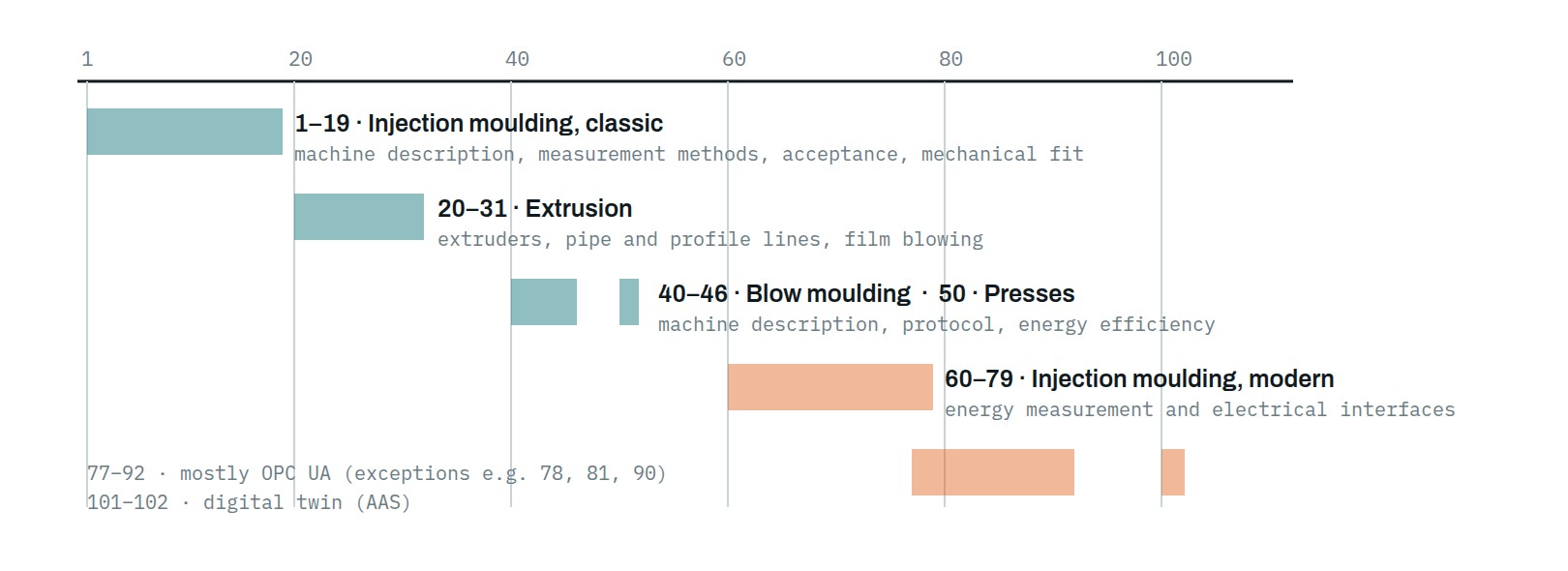
At first glance the numbering looks arbitrary. Why is the dry cycle in number 6, energy in 60, the robot in 67? The numbering does not form a strict, official thematic system, but historically well recognisable groups have emerged within it. The figure below is therefore a map for orientation, not a classification rule: the ranges overlap, and there are recommendations that EUROMAP's own list files under a general category.
Machine characterisation and machine acceptance
This is the oldest and least known group, yet it is the most important one at machine acceptance. These recommendations describe how to measure a machine's characteristics so that the value can be compared independently of the manufacturer. They are the tools for comparing apples with apples.
| Recommendation | Year | What it covers |
|---|---|---|
| EUROMAP 1 | 1983 | Description and characterisation of injection moulding machines, including how the machine size is stated. |
| EUROMAP 2 | 1996 | Mould mounting and connection dimensions. The stroke definitions of the other recommendations also refer to this. |
| EUROMAP 4 | 1994 | Determination of the actual injection efficiency. |
| EUROMAP 5 | 1994 | The key production data to be recorded in the production report. |
| EUROMAP 6 | 2007 | Measurement of the dry cycle time. This is how the speed of the clamping unit can be compared. |
| EUROMAP 7 | 1995 | Determination of the maximum clamping force. |
| EUROMAP 8 | 1974 | Determination of the nominal opening force. |
| EUROMAP 9 | 1998 | Checking the parallelism of the platens during clamping. |
| EUROMAP 10 | 1975 | Testing of injection moulding machines, general rules. |
| EUROMAP 11 (parts 1–5) | 1993 | Automatic mould change: mechanical interfaces, hole pattern, energy and electrical connections, ejector coupling. |
| EUROMAP 19 | 1995 | Determination of the plasticising capacity. |
| EUROMAP 61 | 1994 | Definitions of the operating modes. |
| EUROMAP 64 / 68 / 69 | 2008 | Warning, prohibition and mandatory signs, pictograms. |
| EUROMAP 65 | 2006 | User identification and manufacturer parameter identifiers. Every major machine manufacturer received its own identifier, which distinguishes them in data exchange. |
If four recommendations are worth highlighting for machine acceptance, it is these four: number 7 for the maximum clamping force, 6 for the dry cycle time, 9 for platen parallelism and 19 for the plasticising capacity. If these appear in the acceptance report, then at least the measurement method will not be a point of dispute, because measurements are taken according to a pre-agreed, jointly referenceable procedure. The acceptance limits and the measurement conditions can of course still be argued over; those have to be recorded separately.
For requests for quotation and acceptance reports
- Ask for the clamping force, dry cycle time and plasticising capacity figures to be stated with reference to the relevant EUROMAP measurement method.
- For a larger machine or a tight-tolerance product, also ask for the platen parallelism to be checked at acceptance.
- If you are planning automatic mould change, the mechanical and energy connection requirements of the 11 series must already be built into the mould design.
Electrical and mechanical interfaces
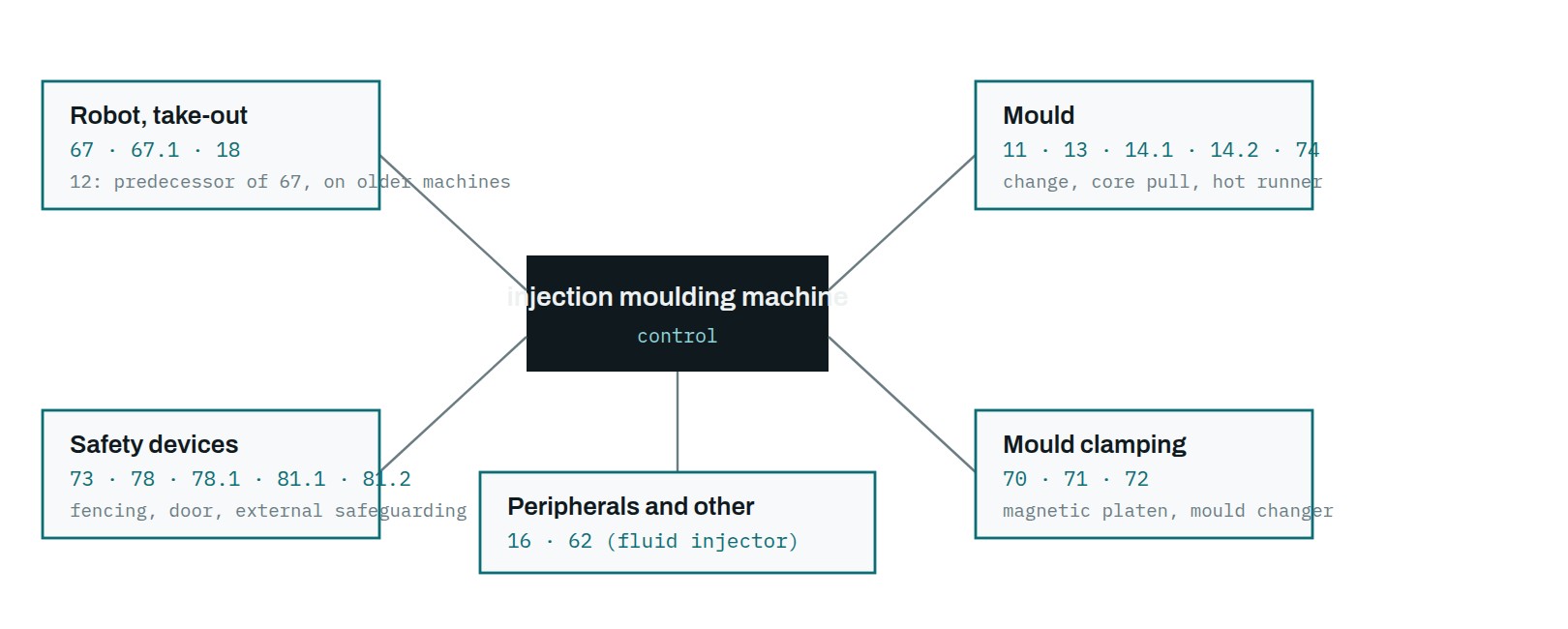
This is the largest group and, in practice, the most frequently used. These decide whether the cell built around the machine comes together.
| Recommendation | Release | What it covers |
|---|---|---|
| EUROMAP 67 | v1.11 2015 | The electrical interface between the machine and the part-removal robot, the de facto worldwide standard for robot connection. It defines the plug and socket design, the handling of the dual-channel safety signals, and the handshake signals: mould closed or open position, enabling of operation, ejector and core puller positions, intermediate mould opening and the reject signal. |
| EUROMAP 67.1 | v1.6 2015 | The same for shuttle and rotary table machines. |
| EUROMAP 12 | v1.7 2015 | The predecessor of 67, for the same purpose. It is still alive on old machines, so it has to be reckoned with in retrofits: a new robot can often only be connected to an old machine via an adapter. |
| EUROMAP 18 | 1994 | Mechanical fitting between the machine and the part-removal equipment. |
| EUROMAP 13 | 2009 | Electrical interface for core pullers. |
| EUROMAP 14.1 / 14.2 | 2009 | Interface for hot runners and mould heating, for thermocouples and heating elements. |
| EUROMAP 16 | 2009 | Analogue or digital electrical connection of peripherals. |
| EUROMAP 62 | 2014 | Interface between the machine and the fluid injector (for example gas injection). |
| EUROMAP 70 | 2009 | Interface between the machine and the magnetic mould clamping system. |
| EUROMAP 71 | v1.5 2015 | Interface between the machine and the mould changing equipment. |
| EUROMAP 72 | 2006 | Integration of magnetic platens into horizontal injection moulding machines. |
| EUROMAP 73 | 2009 | Interface between the machine and external safety devices. |
| EUROMAP 74 | v1.3 2020 | Interface for electrically driven cores. |
| EUROMAP 78 / 78.1 | 2020 | External safety devices, for single- and double-acknowledgement systems respectively. The modern successor to 73. |
| EUROMAP 81.1 / 81.2 | 2024 | The electrical interface for the safety signals only, for the case where all other data already travels over OPC UA. The newest member of the group. |
Where a version number appears in the table, it is the current release. Where only a year is given, it is the year the recommendation was published according to the EUROMAP list. The two often do not coincide, because a recommendation published in 2009 may have a current version from 2020. In a contract, always write the specific version, not just the number.
The very existence of the 81 series says something about the direction of the system. 81 is the interface for the safety signals only, and it can be used when the non-safety signals already travel over another interface, typically OPC UA. This is not an after-the-fact interpretation: EUROMAP 79 itself states that it does not carry the safety signals over OPC UA, and that for those the electrical interface defined in 81 must be used. So 81 sorts out the remainder that stays hard-wired even when everything else no longer is.
The connector is also part of the recommendation
In these recommendations it is not only the meaning of the signals that is fixed, but the physical connector as well: the housing size, the number of poles of the insert, the cross-section of the contacts. This is what makes the system work in practice. EUROMAP's own supplier list states this in a single sentence: the connectors of the manufacturers listed on it are interchangeable with each other. In other words, you do not have to buy the machine-side and robot-side connectors from the same brand.
The table below summarises which recommendation calls for which connector family. The specific type designations and part numbers per manufacturer can be found in EUROMAP's continuously updated supplier list.
| Recommendation | Connector | Note |
|---|---|---|
| EUROMAP 12 | 32-pole A | The old robot interface. |
| EUROMAP 13 | 16-pole A | Core pullers. |
| EUROMAP 14.1 | 16-pole A | Thermocouples. |
| EUROMAP 14.2 | 16-pole E | Heating elements. For its 35 A variant, a 6-pole high-current insert. |
| EUROMAP 16 | 8-pole D 10-pole A | Two variants: version A is an 8-pole D, version B a 10-pole A. |
| EUROMAP 62 | 32-pole A | The same connector as for 12. |
| EUROMAP 67 / 67.1 | 50-pole D | The insert also has a "Z" variant. |
| EUROMAP 71 | 50-pole D | The same connector as for 67. |
| EUROMAP 70 | modular | 12-pole inserts, four-module frame, M25 housing. |
| EUROMAP 73 | modular | 12-pole inserts, four-module frame, M25, 1.0 mm² contacts. |
| EUROMAP 74 | modular | 12-pole inserts, four-module frame, M32 housing. |
| EUROMAP 78 | modular | 12-pole inserts, three-module frame, M32 housing. |
| EUROMAP 81.1 | modular | 8-pole insert, two-module frame. For one safety device. |
| EUROMAP 81.2 | modular | 12-pole and 8-pole inserts, two-module frame. For two separate safety devices. |
| EUROMAP 28 | 6-pole E | Extrusion: measuring wheel, with four connection points. |
| EUROMAP 29 | 24-pole E | Extrusion: downstream equipment after the haul-off, with four connection points. |
| EUROMAP 27.1 | modular | Extrusion: size 10 housing with CAN and signal inserts, in four connection variants. |
Two things are immediately apparent from this. One is that 67 and 71 use the same 50-pole D connector, just as 12 and 62 use the same 32-pole one: the connector alone therefore does not identify the interface, the wiring does. The other is that for the newest recommendation, the 2024 series 81, far fewer suppliers appear on the list than for the old ones. With a new interface this should be treated as a procurement risk, and before ordering it is worth checking who can actually supply.
Energy efficiency
Two measurement recommendations each for injection moulding and blow moulding machines, with the same logic: consumption is stated relative to the mass of material processed, on a kWh/kg basis, under fixed test conditions. These are complemented by the 90 energy label, which is not a measurement method but a uniform presentation of the measured result.
| Recommendation | Year | What it covers |
|---|---|---|
| EUROMAP 60.1 | 2013 | Determination of the energy efficiency class of the injection moulding machine on a kWh/kg basis. Separate class tables apply to screw diameters of 25 mm and above, and below 25 mm. |
| EUROMAP 60.2 | 2013 | Determination of the product-related energy consumption. An official Excel calculation template comes with it. |
| EUROMAP 46.1 / 46.2 | 2014 | The same for blow moulding machines, likewise with its own Excel template. |
| EUROMAP 90 | 2014 | Energy efficiency label. |
The most common misunderstandingThe efficiency class according to 60.1 applies to the machine, not to the cell, and it is measured under fixed test conditions. It is good for comparing two machines of comparable size and category before purchase. Consistent with this, separate class tables apply to screw diameters of 25 mm and above, and below 25 mm. For your own operating consumption, 60.2 gets you closer, with your own product and material, but even that is not a direct electricity bill estimate.
When buying a machine, this difference is measurable in money. The class shown in the catalogue is a comparison tool; the product-related measurement gets you closer to real operating consumption. If you are seriously comparing two manufacturers' offers, ask for both.
OPC UA and Industry 4.0
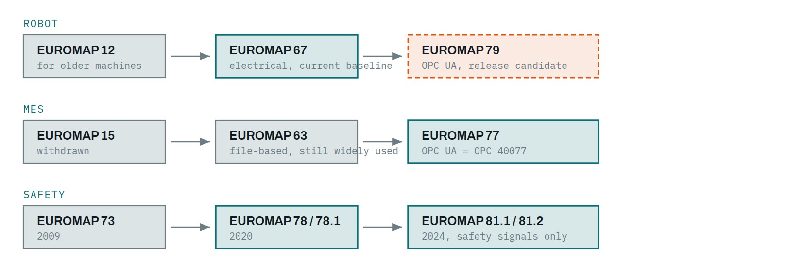
In data exchange between the machine and the MES, the most important generational shift of the past ten years has been the move from file-based interfaces to OPC UA information models. The earlier EUROMAP world was more varied than that: among the old recommendations there are electrical signal interfaces, CANopen solutions and real-time Ethernet as well. What makes the OPC UA-based recommendations new is that they do not merely describe a data format, but also define the properties, states and methods with which a machine or peripheral appears on the network.
| Recommendation | Release | What it covers |
|---|---|---|
| EUROMAP 83 | R1.03 2021 | General type definitions. The common foundation of the entire OPC UA family; every other part builds on it. |
| EUROMAP 77 | R1.01 2020 | Data exchange between the injection moulding machine and the MES. This is the standardised route for machine data acquisition: production control, OEE calculation, traceability. Identical to the OPC 40077 and VDMA 40077 specifications. |
| EUROMAP 79 (release candidate) | RC 1.00.06 2024 | Data exchange between the injection moulding machine and the robot over OPC UA, the digital future of 67. The first release candidate appeared in 2021; the current updated version dates from March 2024. Not yet a final release. |
| EUROMAP 82.1 | R1.01 2020 | Peripherals: temperature control units. |
| EUROMAP 82.2 | R1.00 2021 | Peripherals: hot runner controllers. |
| EUROMAP 82.3 | R1.02.0 2025 | Peripherals: LSR dosing systems. Identical to OPC 40082-3 Release 1.02.0 and the VDMA 40082-3:2025-04 edition. |
| EUROMAP 82.4 | v1.0.1 2026 | Peripherals: feeding and dosing systems. |
| EUROMAP 82.5 (release candidate) | RC 1.0.0 2024 | OPC UA model for moulds. This is the step towards the smart mould. |
| EUROMAP 82.6 | v1.0.0 2026 | Peripherals: granulate dryers. |
| EUROMAP 84.1–84.12 | R2.00 2022 | Extrusion, for the complete line: extruder, haul-off, melt pump, filter, die, pelletiser, cutter, calibrator, corrugator, calender. |
| EUROMAP 86.1 (release candidate) | RC 1.00.01 2022 | Material supply systems, with order management. |
| EUROMAP 87 (release candidate) | RC 1.0.0 2024 | Particle foam machines (EPS, EPP). |
| EUROMAP 91 (release candidate) | RC 1.0.0 2024 | Winders. |
| EUROMAP 92.1 | v1.0.0 2026 | Flexible PUR foam cutting machines. |
One practical conclusion from this: if a manufacturer says "we support OPC UA", that in itself is not an answer. The question is which information model it supports. A proprietary, manufacturer-specific OPC UA server is just as closed a system as an old serial protocol, only in more modern packaging. Support for 77, on the other hand, provides a standardised basis for integration between different manufacturers' machines and MES systems, provided that both sides support the same information model and a compatible release of it.
Digital twin: the newest direction
The newest branch, launched in 2025, is the Asset Administration Shell. The idea is that every asset should have a standardised, machine-readable digital datasheet, which is not sent over as a PDF but exists as a queryable data structure.
| Recommendation | Release | What it covers |
|---|---|---|
| EUROMAP 101.1 | R1.0 2025 | AAS submodel for mould identification. |
| EUROMAP 101.2 (draft) | Draft 1.0 2026 | AAS submodel for the technical data of the mould. Still a draft. |
| EUROMAP 102 (draft) | Draft 1.0 2026 | AAS submodel for the technical data of the injection moulding machine, effectively the digital machine datasheet. Still a draft. |
Today this is more a question of future-proofing and roadmap than a general baseline procurement requirement. It is worth knowing about, though, because it signals where the system is heading: in the future the mould and the machine will not only exchange signals, but also structured data about themselves. Anyone buying a machine now for ten years would do well to ask whether the control system will be expandable in this direction.
Extrusion, blow moulding, presses
Injection moulding is the most elaborated area, but not the only one. Most of the traditional, non-OPC UA-based extrusion and blow moulding recommendations are considerably older, yet machine descriptions and line interfaces still refer to them today.
Extrusion
| Recommendation | Year | What it covers |
|---|---|---|
| EUROMAP 20 | 1975 | Description and characterisation of screw extruders. |
| EUROMAP 21 | 1978 | Measurement and control of extruders. |
| EUROMAP 22 | 1977 | Testing of extruders. |
| EUROMAP 23 | 1976 | Blown film lines. |
| EUROMAP 25 | 1977 | Pipe and profile production lines. |
| EUROMAP 26 (parts 1–3) | 1996 | Protocol between the line and the host computer. |
| EUROMAP 27.1–27.6 | 2007 | CANopen profiles for downstream extrusion equipment in six parts: general definitions, haul-off, corrugator, saw, co-extruder, calibration table. |
| EUROMAP 28 | 2007 | Pipe and profile lines: the electrical interface of the line-speed measuring wheel. |
| EUROMAP 29 | v2.3 | Pipe and profile lines: the discrete electrical interface of CANopen equipment downstream of the haul-off. |
| EUROMAP 31 | v1.1 2025 | Melt temperature measurement in extrusion. The newest member of the group. |
| EUROMAP 84.1–84.12 | R2.00 2022 | The OPC UA model of the extrusion line. Covered in detail in the OPC UA chapter. |
Blow moulding and presses
| Recommendation | Year | What it covers |
|---|---|---|
| EUROMAP 40 | 1974 | Description and characterisation of extrusion blow moulding machines. |
| EUROMAP 42 | 1999 | Extrusion blow moulding machines: centre distances of the blow heads. |
| EUROMAP 45 | 1993 | Protocol between the blow moulding machine and the host computer. |
| EUROMAP 46.1 / 46.2 | 2014 | Energy efficiency of blow moulding machines: machine-related and product-related consumption respectively. Covered in detail in the energy chapter. |
| EUROMAP 50 | 1988 | Description and characterisation of compression and transfer moulding presses. |
Handle old figures with careIn this group several recommendations date from the 1970s, and some of them are only available in scanned form. Figures read out of them should be verified against the original document before they end up in a contract.
Legacy protocols, for retrofits
If you are connecting an existing machine fleet to a network, these are the ones you will run into.
| Recommendation | Year | What it covers |
|---|---|---|
| EUROMAP 15 (parts 1–8) (withdrawn) | 1992 | Protocol between the injection moulding machine and the host computer. Withdrawn; its successor is 63. |
| EUROMAP 17 | 2007 | Protocol between the machine or host computer and peripherals, with a separate parameter list. |
| EUROMAP 63 | 2000 | File-based data exchange interface. Injection moulding MES systems used this for decades, and it still runs in many plants today. Its successor is the OPC UA-based 77. |
| EUROMAP 66 | 2002 | Peripheral communication, with heating and cooling profiles. |
| EUROMAP 75 (parts 1–3) | 2012 | Peripheral communication over real-time Ethernet, with a measuring amplifier profile. |
The most important question in a retrofit is usually not which protocol runs on the old machine, but whether the control system can output data at all. If it cannot, data acquisition can be solved with external sensors and signal tapping, which is no longer a EUROMAP question but a project question.
How to use this when requesting quotations
Knowing EUROMAP is good for exactly one thing when requesting quotations: putting the comparison on a common footing. If two offers refer to the same recommendation, to the same release of it and to comparable test conditions, then their figures can meaningfully be placed side by side. If neither refers to it, you do not know what you are comparing with what.
Five questions that are always appropriate
- According to which recommendation was the energy figure measured, and can the measurement report be provided? (60.1 for the machine, 60.2 for the product)
- Were the clamping force, dry cycle time and plasticising capacity figures produced according to the relevant measurement method? (7, 6, 19)
- Which robot interface does the machine come with, and how much does it cost to add later? (67, and in the future 79)
- Which information model does the control system serve towards the MES, and is it manufacturer-specific? (77, or something proprietary)
- Planning a new robot for an existing machine? Check whether it has a 12 or a 67 interface, because that decides whether you need an adapter.
And a remark in the opposite direction, which is at least as important: EUROMAP conformity in itself is not a certificate of quality. Having a 67 connector on a machine does not make it a good machine. The recommendations provide comparability and connectability, not performance.
Where you meet this in practice
The recommendations above are not theoretical questions. With the machines and peripherals distributed by CIS, every group comes up somewhere:
- PowerJet injection moulding machines: the side of machine characterisation, energy figures and robot connection.
- Samfacc linear part-removal robots and Borunte 6-axis robots: fitting to the machine is precisely a question of the 67 interface. A linear robot for simple part removal, a 6-axis one for more complex tasks.
- MARSE temperature control units: the territory of the OPC UA model according to 82.1, if you want to connect the temperature control unit to data acquisition as well.
- iTech industrial chillers: important parts of the total energy demand of the production cell and the plant, but their consumption must be treated separately from the injection moulding machine's class according to EUROMAP 60.1. The measurement boundary of 60.1 explicitly excludes the heat transferred into the machine's cooling medium.
- PowerJet EB blow moulding machines: the territory of recommendations 40, 42, 45 and 46.
If an interface question arises for a specific machine or an existing machine fleet, it is worth asking before the robot or the peripheral is ordered. The price of an adapter and the cost of an integration that set off in the wrong direction are not the same order of magnitude.
For specific interface or machine questions you can ask in the plAstIc expert chat — the EUROMAP recommendations are part of its knowledge base.
Sources
Source and further information: www.euromap.org
This article is a summary of the EUROMAP technical recommendations in our own words. The recommendations can be downloaded free of charge from the EUROMAP website, but they are protected by copyright, so the details of the pin assignments, connector tables and measurement procedures are not reproduced here, only a description of their content.
- EUROMAP: Technical Recommendations, the complete list of recommendations with downloadable documents.
- EUROMAP: Overview OPC UA Specifications, with the release status of the OPC UA-based recommendations.
- The EUROMAP technical commission, VDMA, Lyoner Str. 18, Frankfurt am Main.
- The identically numbered specifications of the OPC Foundation and the VDMA (OPC 40077, VDMA 40077 and the rest).
Take the essentials with you!
Enter your details and we'll email you the download link.
Got a question? We can help!
Get in touch and our experts will help you choose the right solution.
Contact →